- Veterinary View Box
- Posts
- Getting ready to do cardiac CT or cardiac MRI....
Getting ready to do cardiac CT or cardiac MRI....
Veterinary Radiology & Ultrasound, 2020.
Matthias Dennler, Marco Baron Toaldo, Mariano Makara, Ines E. Lautenschläger, Gianna Ribbers, Adriano Wang-Leandro, Maja Waschk, Henning Richter, Tony M. Glaus.
Background
Cardiac magnetic resonance imaging (cMRI) is increasingly used in veterinary medicine to assess complex cardiac conditions in dogs. Proper plane alignment is crucial for reproducible heart measurements, but no standardized method for defining imaging planes has been established. This study aimed to develop a standardized flowchart for canine cMRI, validate its reproducibility using cardiac CT simulation, and evaluate the time required for plane acquisition.
Methods
Six healthy Beagle dogs underwent cardiac CT imaging, which was used to simulate cMRI examinations. Six operators (three radiologists, one cardiologist, one imaging resident, and one technician) performed plane definition using a standardized flowchart. Plane quality was assessed subjectively and objectively through linear cardiac measurements. Intraobserver and interobserver reliability were evaluated, and the time required to complete the plane definition process was recorded.
Results
Plane definition quality was high for the left heart but more variable for the right heart. Intraclass correlation coefficients (ICC) for left-sided cardiac measurements were good to excellent (0.789–0.948), but right-sided measurements were less reliable (0.429–0.738). The median time to complete a full examination was 30 minutes initially and decreased to 24 minutes upon repeat testing, with significant variation between operators. The right ventricular outflow tract (RVOT) was the most challenging plane to define, requiring the longest acquisition time and exhibiting the lowest reproducibility.
Limitations
The study was limited to a small, homogeneous population of healthy Beagle dogs, which may not fully represent anatomical variations across different breeds or diseased hearts. Additionally, CT-based simulation may not fully replicate real-time cMRI acquisition challenges.
Conclusions
A standardized cMRI plane acquisition protocol can be effectively implemented and is highly reproducible for left-sided cardiac structures but less so for the right heart. Training improves efficiency and accuracy. These findings provide a foundation for optimizing cMRI protocols in clinical and research settings, improving consistency in canine cardiac imaging.

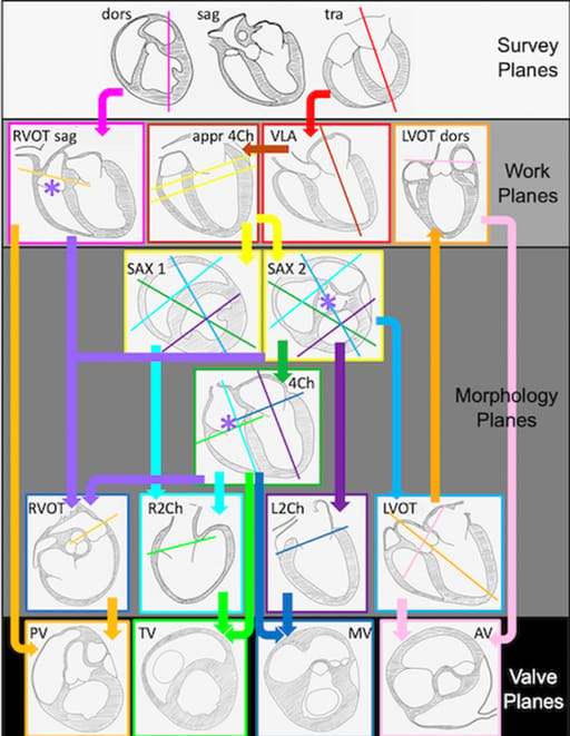
Flow chart for the acquisition of two-dimensional planes. A step-by-step approach for the navigation through the chart is crucial. Translation and rotation in the previous plane only allows rapid and reproducible definition of the following plane. Survey planes are acquired in the three principal anatomic planes of the heart given its oblique position within the thorax: dorsal (dors), sagittal (sag), and transverse (tra). Work planes do not have profound diagnostic value but facilitate planning: appr4Ch; approximate four chamber plane; LVOTdors, dorsal plane of the left ventricular outflow tract; RVOTsag, sagittal plane of the right ventricular outflow tract; VLA, vertical long axis plane. Morphology planes serve for functional and morphological assessment: 4Ch, four chamber plane; L2Ch, left ventricular two chamber plane; LVOT, left ventricular outflow tract plane; R2Ch, right ventricular two chamber plane; RVOT, right ventricular outflow tract plane; SAX, short axis planes at two levels. The valve planes fulfill requirements for flow measurements and morphologic assessment: AV, aortic valve plane; MV, mitral valve plane; PV, pulmonary valve plane; TV, tricuspid valve plane. VLA is defined in the survey plane tra (red arrow). VLA defines appr4Ch (brown arrow). The intersection of appr4Ch and VLA defines the true vertical long axis. SAX is perpendicular to this important line (yellow arrows). Rotation of the plane around the true vertical long axis produces 4Ch (dark green arrow), L2Ch (dark purple arrow), and LVOT (blue arrow). The remaining work planes are then found in the dors survey plane for RVOTsag (pink arrow) and in LVOT for LVOTdors (orange arrow). R2Ch is found in SAX (light blue arrow). Three points define RVOT: aortic valve, pulmonary valve and tricuspid valve (light purple arrows). LVOT and LVOTdors define AV (light pink arrows), 4Ch and L2Ch visualize MV (light blue arrows). PV is visible in RVOT and RVOTsag (dark yellow arrows) and TV in 4Ch and R2Ch (light blue arrows) [Color figure can be viewed at wileyonlinelibrary.com]
How did we do? |
Disclaimer: The summary generated in this email was created by an AI large language model. Therefore errors may occur. Reading the article is the best way to understand the scholarly work. The figure presented here remains the property of the publisher or author and subject to the applicable copyright agreement. It is reproduced here as an educational work. If you have any questions or concerns about the work presented here, reply to this email.